frodo
Senior Member
- Joined
- Aug 5, 2008
- Messages
- 3,067
- Reaction score
- 1,204
http://www.bing.com/images/search?q=4%27%27+snap+lock+duct&view=detailv2&&id=383DCFF026A55F0F64115E8062EE0B0F7EAB0200&selectedIndex=7&ccid=%2fkx4xnxH&simid=607986508808257767&thid=OIP.Mfe4c78c67c473e97cb564593852e5429o0
http://www.bing.com/images/search?q=metal+duct+tape&view=detailv2&&id=37CA3F0981E2A688BC7895A77729A973799C2928&selectedIndex=7&ccid=BJjEm5h2&simid=608018549255570892&thid=OIP.M0498c49b98768a417b22871a6446419ao0
http://www.bing.com/images/search?q=duct+crimper+tool&view=detailv2&&id=ABC4C8B272250ABC39311BBC6831A98ED41BE4A1&selectedIndex=10&ccid=4oygT29L&simid=608039994025512691&thid=OIP.Me28ca04f6f4b629b0ce62711e768dbc1o0
http://www.bing.com/images/search?q=duct+insulation+wrap&view=detailv2&&id=2DEA4C91B0DBB85957DBBE879B5781018B0531DE&selectedIndex=0&ccid=EL1X7Mtf&simid=608006871246505438&thid=OIP.M10bd57eccb5fc1c95e2dd9bcdedd0af8H0
the above items, snap lock duct
hvac metal tape
crimpers
insulation
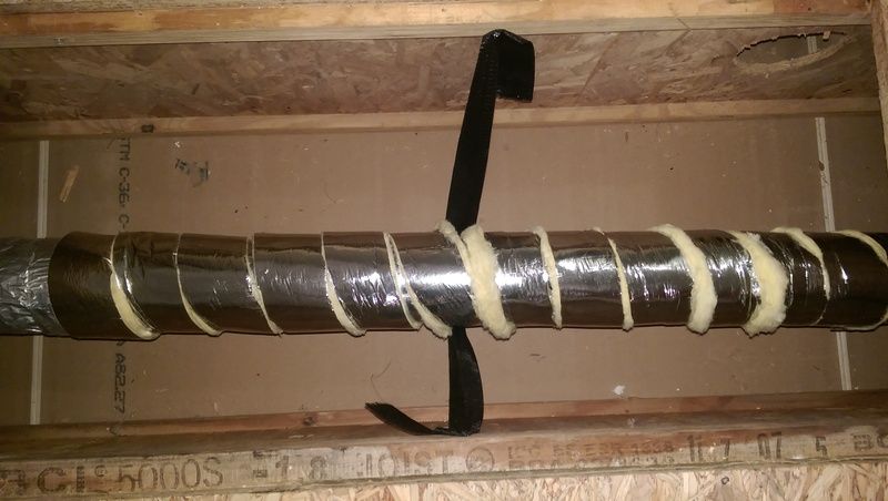
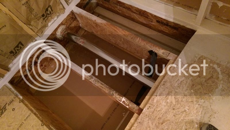
use these items, to run that exhaust vent, what you curently have is not ment for what it is being used for
that is a dryer vent,,
http://www.bing.com/images/search?q=metal+duct+tape&view=detailv2&&id=37CA3F0981E2A688BC7895A77729A973799C2928&selectedIndex=7&ccid=BJjEm5h2&simid=608018549255570892&thid=OIP.M0498c49b98768a417b22871a6446419ao0
http://www.bing.com/images/search?q=duct+crimper+tool&view=detailv2&&id=ABC4C8B272250ABC39311BBC6831A98ED41BE4A1&selectedIndex=10&ccid=4oygT29L&simid=608039994025512691&thid=OIP.Me28ca04f6f4b629b0ce62711e768dbc1o0
http://www.bing.com/images/search?q=duct+insulation+wrap&view=detailv2&&id=2DEA4C91B0DBB85957DBBE879B5781018B0531DE&selectedIndex=0&ccid=EL1X7Mtf&simid=608006871246505438&thid=OIP.M10bd57eccb5fc1c95e2dd9bcdedd0af8H0
the above items, snap lock duct
hvac metal tape
crimpers
insulation
use these items, to run that exhaust vent, what you curently have is not ment for what it is being used for
that is a dryer vent,,
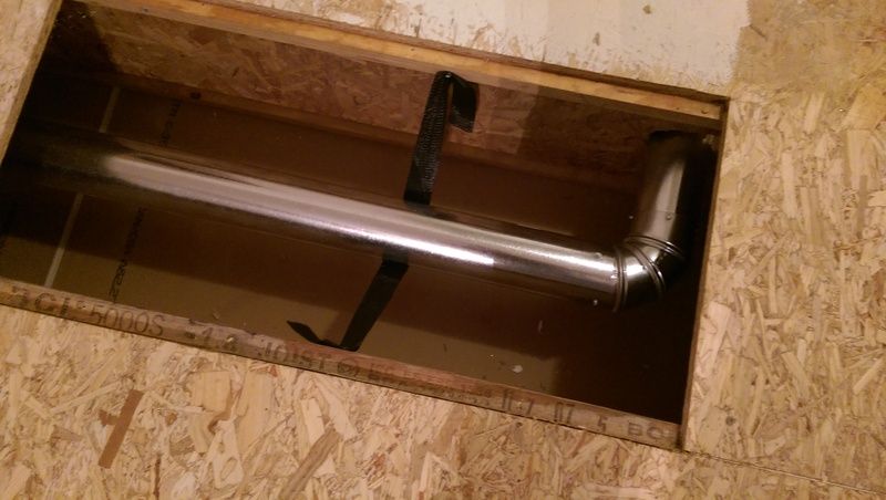
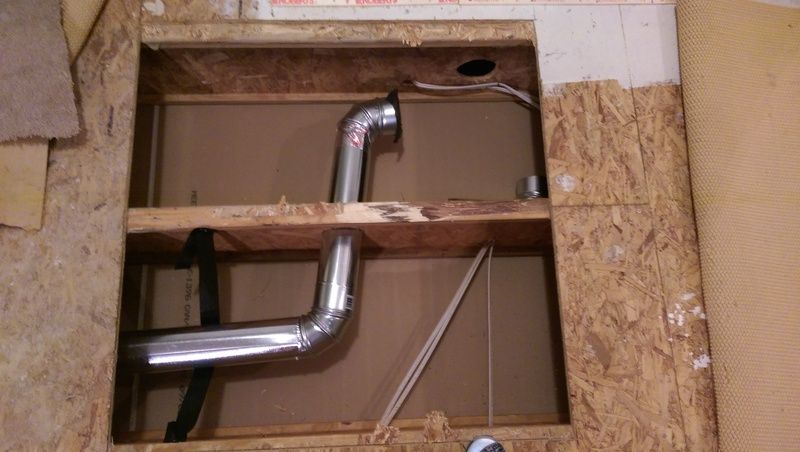
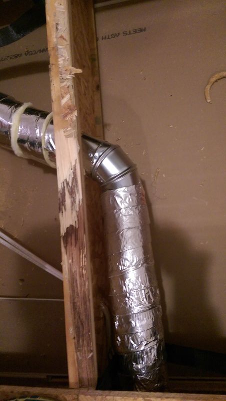
 Edit: I guess I could always just leave the pipe completely exposed instead of routing through the walls even though that isn't aesthetically pleasing.