Switched Lights in an Outlet Circuit

House Repair Talk

Help Support House Repair Talk:

This site may earn a commission from merchant affiliate links, including eBay, Amazon, and others.

drewje

New Member
Joined
Jul 21, 2009
Messages
2
Reaction score
0
Hello all - first time here and looking for some help with a wiring issue. My goal is to wire a switched branch of under cabinet lights from a circuit of always-on power outlets.

If I was just adding this to the end of the circuit, it would be easy, but I can't find the end of the circuit, so the switch will be going in the middle somewhere. I want to replace an outlet and have the power continue full time along the rest of the outlet string. I've attached a drawing that shows what I'm thinking, with the switch replacing one outlet.

3743180248_b2847f07bf_b.jpg


So, my question is how to wire that bank of lights so the power continues to the other outlets, but I still have a branch that is switched for the lights. Any thoughts?

Thanks,

Drew
 
Drew:

You need to understand that, except for switched outlets, and switched lights, most of the circuits in a house are run in parallel.

For example, in the drawing you provided, you're showing all the outlets wired in series.
This can't be the way your house is wired because there would be no power to the second outlet unless something is plugged into the first outlet.

The better way to understand the wiring of the outlet circuit in your house would be to draw a black (or red) wire running above ALL of the outlets and a white wire running below all of the outlets.

Then draw a black wire connecting the right side of each outlet to the black wire above all of the outlets and a white wire connecting the left side of each outlet to the white wire below all of the outlets. When you make connections like this, you will have a total of 3 black wires connected at a wire nut in the electrical box and three white wires connected with a wire nut in the electrical box. The short black wire and short white wire going to the outlets are called "pigtails". Thus, each outlet is connected in PARALLEL with all of the others so the each outlet can deliver power to an appliance plugged into it (even if nothing is plugged into the outlets on either side of it).

That would be exactly what you have wired in your house now, except that some of the outlets might actually be on a different breaker, and be powered by a red wire rather than a black one.

To replace one of the outlets with a switch for the cabinet lights, you'd simply take the outlet out and connect the black wire that formerly went to the outlet to one screw on the switch. Now run ANOTHER BLACK WIRE from the other screw on the switch to your string of under cabinet lights. Connect that new black wire with pigtails to each of your undercabinet lights so they're all wired in PARALLEL. (Otherwise if one light burns out, then that burnt out bulb breaks the circuit, and all of the lights will go out.) So, that new black wire is connected with pigtails to each of the undercabinet lights, and each of the under cabinet lights is connected with pigtails to a white wire that goes back to the electrical box with the switch in it and connects to the white wire that formerly went to the left side of the outlet.

In this way, you can still have power to each of the outlets, but you can switch the under cabinet lights on and off with a switch mounted in one of the old outlet boxes.

Just redraw the diagram above with all of the outlets in parallel instead of series, and all of the new lights you intend to install in parallel instead of series, and it will then occur to you that the difficulty you had in understanding what to do originated with your misconception that everything was wired in series. It isn't. All the outlets should be wired in parallel and all the lights should be wired in parallel.
 
Last edited:
Drew:

Here's a blurb I wrote years ago for a lady who wanted to know how to connect a dryer plug and cord so that she could move her dryer to clean behind it. It explains all the basics of house wiring, and I think that if you read it, you would better understand how your house is wired and thereby be safer when making any changes to your house's wiring:

220 volt power that is supplied to homes is delivered via two power lines and a neutral wire. The two power lines each carry 110 volts AC, but they are "out of phase" by 180 degrees. That is, when one power line is at +110 volts with respect to the white neutral wire, the other power line will be at -110 volts with respect to the white neutral wire, and vice versa. So the voltage you would measure between the two power supply lines would be 220 volts AC. On appliance wiring diagrams, the two power lines will typically be called "L1" and "L2" for "Line 1" and "Line 2". In practice, Line 1 and Line 2 will ALWAYS be the red and black wires (meaning the insulation on them will be red or black in color), and the neutral wire is ALWAYS white. Grounding wires will be green or bare (with no insulation).

The technically incorrect but easiest way to think about this is that the power comes "in" on the red and black wires and goes out on the white wire. Obviously it doesn't, but that way of thinking about it will at least help you better understand house and appliance wiring. Also, if the black supply wire is feeding a 110 AC voltage sine wave into the white "return" wire and the red "supply" wire is feeding an equal but opposite voltage into that same white "return" wire, then theoretically, there should be no voltage or current in the white wire because the opposite voltages (and hence currents) would all cancel out in that white wire. If all electrical loads were purely resistive, like light bulbs and toasters and electric ranges and coffee makers, then there would be very little current or voltage in that white wire. However, in the real world there are electric motors and television sets and computer monitors, all of which have some "impedance". In an electric motor, for example, the magnetic fields created by the electric motor windings impeded the flow of current through the motor windings, so the motor windings cause the current sine wave coming out of the motor to lag behind the applied voltage sine wave. Also, television sets and those old CRT style computer monitors have huge capacitors in them, and that causes the current sine wave coming out of those computer monitors to actually preceed the applied voltage sine wave. So, even though the red and black wires carry equal and opposite 110 AC voltage sine waves, then timing differences caused by "reactive" loads like electric motors and television sets can result in there being significant voltage and current in the white wire. So, treat every wire as having dangerous voltage in it.

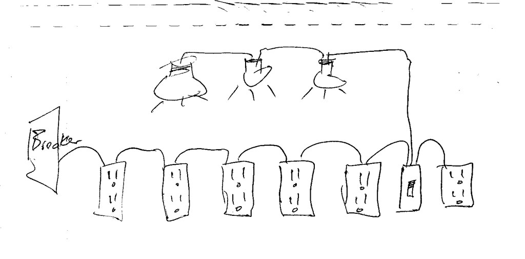
The standard 110 volt circuits for the ceiling lights or electric outlets in your house are made by connecting those circuits between the white neutral wire and EITHER the main red wire OR the main black wire coming into your house. All of those connections are made in your electrical panel and a fuse or circuit breaker is provided for each such circuit in your house. So, some of the 110 volt circuits in your house that go to lights or electric outlets are powered by the red wire, and some are powered by the black wire. As long as the circuit is between the red wire and the white wire, or between the black wire and the white wire, you have a 110 volt AC circuit. If you put a 15 amp fuse or breaker on that 110 volt circuit in the panel, then you have a 110 volt 15 amp circuit, and normally the circuits going to the lights, ceiling fans and electrical outlets in your house will be 110 volt 15 amp circuits.

220 volt circuits for the house's electric stove and electric clothes dryer are made by connecting the circuit between the main black and red wires at the electrical panel. Both the red and black wires carry 110 volts AC with respect the the white neutral wire, but because they're 180 degrees out of phase, there's 220 volts AC between the red and black wires. So, if you connect a circuit between the main black and main red wire going into the house, then you have a 220 volt circuit. If you're wiring a range, you normally need a 50 amp circuit, which requires a 50 amp breaker on BOTH the red and black wires going to the range. If you're wiring an electric dryer, you need a 30 amp circuit, so that means you must have 30 amp breakers on both the red and black wires going to the dryer. The fuses and breakers that control the current through every circuit are located inside your house's electrical panel.

When you open a typical electrical panel you'll notice that the fuses or circuit breakers are typically arranged in two vertical rows; one on each side of the panel. Do not assume that one side of the panel is for tapping off the red power line and the other is for tapping off the black power line. The buss bars inside the electrical panel determine what gets connected where, and often breaker positions above one another on the same side of the panel will be connected to opposite voltage sources. This is done so that the circuit breakers can be "ganged together" so that you can't flip the breaker off to one power line going to a stove or dryer without turning the power off to BOTH power lines. In Manitoba, the electrical code requires that circuit breakers for 220V appliances be "ganged" together in this way for safety reasons.

There is a standard wiring convention used when wiring the plugs, receptacles and terminal blocks of 220 volt appliances, all of which will have provision for connecting THREE wires as well as a ground wire. Normally the ground wire terminal will be easy to identify because it will be grounded to the electrical box by an electrical conductor, and the remaining three connection points will be arranged in a row of three connection sites. The wiring convention is that the white neutral wire is ALWAYS connected to the middle terminal in that row of three connection sites, and the red and black wires are connected on either side of it. It doesn't matter which side you connect the red or the black to, as long as the white is in the middle and the red and black are on the outside, you're good to go. If your stove or dryer doesn't come with a cord and you want to connect one to the terminal block of the appliance, the same rule applies, namely "white in the middle, black and red on the outside". If you're wanting to wire a receptacle for a stove or electric dryer, then again, the same rule applies. First identify the ground wire terminal, and the remaining three connection points will be for the red, white and black wires and they should be arranged in a recognizable "row". Always connect the white in the middle of those three sites and the red and black on either side of the white. This point has now been officially hammered into your head; white in the middle, black and red on either side.

Every dryer cord will have 4 prongs sticking out of it. The straight ones are for the red and black wires, the "L" shaped one is for the white wire and the round one is for the ground wire. Range cords also have 4 prongs, but they will use 3 straight prongs for the red, black and white wires and a round one for the ground wire. Configuring the plug and receptacle differently (with an "L" shaped prong instead of a straight one) is done so you can't stick a 30 amp dryer plug into a 50 amp range receptacle or vice versa.

The heating elements in both electric dryers and stoves require 220 volt power, but you still need to run the white wire to the stove or dryer. The reason why is that there will be circuits within the stove or dryer that require only 110 volt power. For example, the electric motor that turns the dryer drum or the light bulb inside an oven will both require 110 volt AC power, not 220 volt power. So, in an electric stove the heating elements will be connected between the red and black wires because they need 220 volts, but the electrical outlets provided for convenience on the stove console will be connected between the white wire and either the red or black power wires, because the convenience outlet is intended to provide power to 110 volt appliances. And, this is also why you can have TWO convenience outlets on a stove instead of just one. One of those convenience outlets will be powered by the black wire, and the other one by the red wire. Since the main black and red wires going to a stove are fused at 50 amps each in the electrical panel, any circuit between the red and white OR black and white wires in the stove will give you a 110 volt 50 AMP CIRCUIT which probably won't stop pumping out the electricity if there's a short somewhere in that circuit, and 50 amps going through wiring rated at 15 amps is a great way to start a fire. That's why for the electric outlets provided for convenience on range cooktops, there will be a 15 amp fuse right in the range somewhere that fuses each convenience outlet down to 15 amps. If you have two cooktop plugs, one will be driven by the red wire and one by the black wire, and each will have a separate 15 amp fuse on it.
 
This web site won't take posts that are longer than 10,000 characters, so I had to break this wiring blurb up into two parts. Here's the last part:

There is also a wiring convention when wiring 110 volt 15 amp electrical outlets. Since those outlets are always connected between either the red and white wire or between the black and white wire, the connection screws on the outlet will be "colour coded" to ensure you connect the right wire to the right screw. You'll notice that the connection screws on the two sides of electrical outlets will be bare brass on one side and chrome plated on the other side of the outlet. The convention is that you connect the dark wire to the dark screw and the light wire to the light screw. That is, the red or black wire gets connected to the brass screw and the white wire gets connected to the chrome plated screw.

The reason for having this convention becomes obvious when you consider the old two prong plugs and two prong receptacles that had both prongs on the plug and both slots in the receptacles the same width.

What would happen if you had a short circuit in an appliance like a hair dryer or kitchen mixer? If you plugged that appliance in with the plug one way (that we'll call "right side up") then the switch would be on the plug prong that connects to the black or red wire in the house wiring, and as long as the appliance was turned off it would pose no risk of shock because the switch would prevent power from getting into the appliance. However, if you were to unplug that faulty appliance and push the plug in "upside down", then the other prong of the plug would be connected to the black supply wire. If there were a short circuit in that appliance, then you could get a shock from touching that appliance even though it was turned off.

The whole idea behind "polarized" plugs and receptacles is to ensure that the black or red wire carrying power to a receptacle will always connect to the prong of the plug that the appliance's ON/OFF switch is on. That way, as long as the appliance was turned off, it posed no risk of shock.

This may seem like a trivial matter, but it isn't. If you have an electric shaver or curling iron you use in a bathroom, and it has a non-polarized plug, then if there's ever a short circuit in that appliance then it can be energized with 110 volt power even when it's turned off. So, you can get a shock just by touching it and a plumbing fixture at the same time.

So, the wiring convention of connecting the dark wire to the dark screw and the light wire to the light screw on an electrical outlet ensures that the red or black power line always goes to the narrower slot on the electrical outlet. And, as long as appliance manufactures follow the same convention and put their ON/OFF switches on the wire going to the narrow prong on the appliance's plug, then you can always turn off the power to an appliance by shutting it off at the ON/OFF switch.
 
Thanks for the information, Nestor. I did get it figured out, and basically did what you said. My drawing was a bit simplistic, I realize now. Each of the single wires I drew were really the black/white pair.

Anyway, you can now see that I have successfully wired the lights in on that side of the kitchen (in Parallel!) with a new wall switch.
3743966336_1cce94ee7a_b.jpg
 
Drewje:
Anyway, you can now see that I have successfully wired the lights in on that side of the kitchen (in Parallel!) with a new wall switch.

What I can see is that you've obviously removed ceramic tiles from that backsplash wall below the cabinets, and I'd repair that drywall before going any further with your work. And, I can see that you've started to remove the ceramic tile backsplash over your stove as well.

If it wuz me, after removing any loose paper, I'd apply some fiberglass mesh drywall joint tape over the areas where the brown paper is showing on that backsplash wall.

I'd apply strips of fiberglass mesh tape in one direction over the brown areas, and then paint that fiberglass mesh tape with white wood glue diluted with water to make it into a paintable consistancy. Then I'd do an encore performance with the strips of mesh going at right angles to the first coat and paint with diluted glue again.

As the glue dries, it'll bond the fiberglass mesh to the brown paper of the drywall, thereby replacing the strength lost in the brown areas where the white surface paper is missing. After all, it's the paper on each side of a sheet of drywall that gives the drywall it's strength and rigidity. So, if you can't replace the paper, at least replace the strength of the drywall lost when the paper was torn off.

I wouldn't skim coat that backsplash wall with joint compound until I'd repaired that drywall with fiberglass mesh. But, I'm a perfectionist, and I don't expect everyone else to be as meticulous about the work they do as I am.

And, once you repair the drywall, skim coat, sand, prime and paint, make sure you provide for a FLEXIBLE joint where the counter top meets the damaged drywall wall.

That's because the cabinet (and hence, the counter top) are nailed or screwed to the floor, whereas the backsplash you install will be connected (somehow) to the wall, and there will always be some amount of relative movement between the floor and the wall. And, obviously, that relative movement can be a problem for some materials, like ceramic tile grout that simply doesn't have the elasticity to accomodate ANY relative movement between the cabinet and the wall.

Also, whatever you do, if your intent is to install new ceramic tile on that damaged drywall, ensure that you have a FLEXIBLE joint where that cabinet's countertop meets that damaged drywall wall. And, if there's a kitchen sink out of view in that picture, you need to ensure that the joint between the counter top and the backsplash wall is both flexible and WATER PROOF. Otherwise, any leakage of water into that joint will result in the drywall behind the cabinets deteriorating, especially in the area of the kitchen sink.

Maybe let us know your intentions for the backsplash wall, and what you intend to do at the point where the wall meets the counter top, especially at the area behind any kitchen sink in that counter top. What you do there is important since you need that joint to be both flexible and water proof.
 
Last edited:
Back
Top