I bought a SpeedAire 80 Gallon 7.5hp air compressor. It has a Baldor VL1309 electric motor. I am running it at 220v. It has 3 wire coming out of the compressor to the capacitors. It has one start and two run capacitors and 3 jumper wires. Does anyone know how they should be wired?

You are using an out of date browser. It may not display this or other websites correctly.
You should upgrade or use an alternative browser.
You should upgrade or use an alternative browser.
Wiring Capacitors for Baldor VL1309 Air Compressor Motor
- Thread starter NickCJ7
- Start date


Help Support House Repair Talk:
This site may earn a commission from merchant affiliate
links, including eBay, Amazon, and others.
That's the thing, wire colors are white. I have had it wired and running till the capacitors gave out. When removing the case the capacitors were enclosed in the tabs broke off the capacitors so getting a picture of the wiring was not an option.
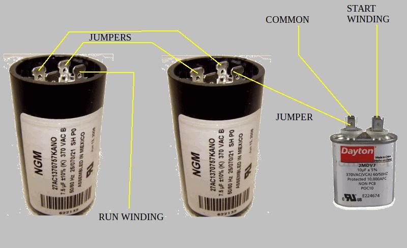
I found a motor like mine that has 3 wires coming out going to 3 capacitors with 3 jumpers:

Now I'm not sure if this is how mine should be wired because I have one start and two run caps and that looks like its two start one run cap. I could be wrong though.
Here is a schematic I've found for my motor, but not being an electrician it makes no sense to me:

Here is a picture of the 3 wires coming from the motor on mine. I numbered them because they are all the same color and I can't make out the markings:

We hooked up #1 as the Common
We hooked up #2 as the Run
We hooked up #3 as the Start
This blew one of the capacitors. If we meter #2 and #3 against #1 and get 2.6ohms. If we meter #2 and #3 we get 0.4ohms.
Which wires would be the Common, Run, and Start?
Someone gave me this as how to wire but I need to know Common, Run and Start.
I found a motor like mine that has 3 wires coming out going to 3 capacitors with 3 jumpers:
Now I'm not sure if this is how mine should be wired because I have one start and two run caps and that looks like its two start one run cap. I could be wrong though.
Here is a schematic I've found for my motor, but not being an electrician it makes no sense to me:
Here is a picture of the 3 wires coming from the motor on mine. I numbered them because they are all the same color and I can't make out the markings:
We hooked up #1 as the Common
We hooked up #2 as the Run
We hooked up #3 as the Start
This blew one of the capacitors. If we meter #2 and #3 against #1 and get 2.6ohms. If we meter #2 and #3 we get 0.4ohms.
Which wires would be the Common, Run, and Start?
Someone gave me this as how to wire but I need to know Common, Run and Start.
Speedbump
Water well etc.
- Joined
- Apr 17, 2009
- Messages
- 672
- Reaction score
- 72
I have been repairing motors for years, but when it comes to the start and run windings, you would need a schematic with the ohm values of each so you can determine which is which. As you can see, the values are not that much different from each other.
If you can find someone who rewinds motors, that person could probably ohm it out and tell you where to wire the caps and how.
I do not rewind, so that's not something I'm familiar enough with to be making any wild guesses.
The other thing that might help is the numbers on the wire insulation. That should mean something to a rewinder. I see a # 5 on one of them and you will notice that two have metal spade connectors and one has it's spade covered with a plastic shield. That too should tell a rewinder something.
Good luck.
Not pretending to be an expert here, but in the absence of exact specs ...
- the run ( main ) winding will always have the higher ohm value
- the start ( auxiliary ) winding will always have the lower ohm value
- you can find the 'common' wire by comparing the ohm readings between all three leads. If in your example one winding is actually 2.6 ohms and the other winding is actually 0.4 ohms, measuring every combination of the three leads should result in one ohm reading that is 3.0 ohms. The wire that is NOT used to get the 3.0 ohm reading is your 'common' wire.
- the 'start' capacitor will be the one with the highest uF rating
and here is a general circuit drawing for single phase capacitor start- capacitor run motors. Note however that the 'hot' side connections are not brought through to your capacitor box leads.

~
- the run ( main ) winding will always have the higher ohm value
- the start ( auxiliary ) winding will always have the lower ohm value
- you can find the 'common' wire by comparing the ohm readings between all three leads. If in your example one winding is actually 2.6 ohms and the other winding is actually 0.4 ohms, measuring every combination of the three leads should result in one ohm reading that is 3.0 ohms. The wire that is NOT used to get the 3.0 ohm reading is your 'common' wire.
- the 'start' capacitor will be the one with the highest uF rating
and here is a general circuit drawing for single phase capacitor start- capacitor run motors. Note however that the 'hot' side connections are not brought through to your capacitor box leads.
~
Last edited:
I believe I've got it figured out. The run capacitor that blew is going to cost another $14. I think I'm just going to take the motor with me to Electric City and see if they know for sure how it's hooked up or can point me to the right direction. I'm not wanting to spend a bunch of money trying to figure it out for myself and really need it back up and running ASAP because it's a life saver while doing the frame up build on my Jeep CJ7 so I just want to get it running.
Is there anyone that anyone knows around the Jacksonville, FL area that is good with these motors? I called Dayton up and they have a few places that do repairs on their equipment around here so I might just take it to them and see if they can help me out.
Is there anyone that anyone knows around the Jacksonville, FL area that is good with these motors? I called Dayton up and they have a few places that do repairs on their equipment around here so I might just take it to them and see if they can help me out.
quackenbush
Member
- Joined
- Jan 16, 2013
- Messages
- 8
- Reaction score
- 2
In the picture you supplied of the three loose "cans", wire connected, the common wire is the plastic coated lead as it connects all three similar plates/poles of all three caps to one motor lead. At least that is if it is correctly wired. The Run wire (O from the wiring diagram) has to be the right-most wire in the pic going to the brown coated cap. The start wire, which goes through the switch has to be the far left lead, (E in the wiring diagram of a start-run cap motor -- the two leads are parallel but one goes thru a centrifugal switch) -- which goes into the two metal cans' similar poles or plates -- which are jumpered of course in parallel.
The three jumpers connected goes to the common motor lead which in the pic has a plastic coating on the connector. The "Run wire" is the O lead in the wiring diagram which goes to one side/plate/pole of the smaller MuF run cap, or in the pic, the brown coated can. I would say you had reversed the start and run leads in order to burn a cap. Trying to run the motor on the larger capacitance start capss could cause overheating. The two larger caps are the start caps. Larger = larger electrolytic, higher capacitance for starting. BTW if you have two starts and a run cap, that is NOT the wiring diagram for your motor. That diagram is for a start-with-cap only motor. No run cap in diag. Get the right PDF one from Baldor who have all the wiring diagram PDFs. Might have to phone and use your spec number to get the model or the new model number. Spec number is on plate on motor. One letter, three numbers. It is vital to know your start from your run wire. O from E. One white wire should have a number on it, probably "1" which the factory can tell you is or is not the start wire. The common wire goes through the windings and should be relatively high resistance across the other wires. The run wire should be the lowest resistance across the common wire.
The three jumpers connected goes to the common motor lead which in the pic has a plastic coating on the connector. The "Run wire" is the O lead in the wiring diagram which goes to one side/plate/pole of the smaller MuF run cap, or in the pic, the brown coated can. I would say you had reversed the start and run leads in order to burn a cap. Trying to run the motor on the larger capacitance start capss could cause overheating. The two larger caps are the start caps. Larger = larger electrolytic, higher capacitance for starting. BTW if you have two starts and a run cap, that is NOT the wiring diagram for your motor. That diagram is for a start-with-cap only motor. No run cap in diag. Get the right PDF one from Baldor who have all the wiring diagram PDFs. Might have to phone and use your spec number to get the model or the new model number. Spec number is on plate on motor. One letter, three numbers. It is vital to know your start from your run wire. O from E. One white wire should have a number on it, probably "1" which the factory can tell you is or is not the start wire. The common wire goes through the windings and should be relatively high resistance across the other wires. The run wire should be the lowest resistance across the common wire.
Wuzzat?
Well-Known Member
- Joined
- Jan 20, 2010
- Messages
- 2,471
- Reaction score
- 176
I always thought that three caps almost certainly need four wires but I don't work much with motors.
Caps can explode: wear face protection if you are going to be hooking up components in this fashion.
Do not end up in the ER or on the evening news.
Caps can explode: wear face protection if you are going to be hooking up components in this fashion.
Do not end up in the ER or on the evening news.
Last edited:
quackenbush
Member
- Joined
- Jan 16, 2013
- Messages
- 8
- Reaction score
- 2
You don't need more than three wires, as one is common to both the run and start caps and the other two are the start and run which can be put across the electrolytic starts in parallel, i.e. to one pole of a jumper-paralleled group of plates or poles, and the other wire, i.e. the run wire can be put across one pole of the run cap. In the Baldor design I have, there are two windings, A and B. One is auxilary the other the main winding. Interestingly BOTH the start and run wires come from the auxilary winding and the common ALSO goes to the auxilary winding. The auxilary winding is NOT cut out in this design at all, but continues to work slightly off phase to the main winding, working with the smaller and lower MuF oil-based capacitor. What cuts out by centrifugal switch is just the large electrolytic capacitor bank and its wire, in the case the E wire or so called Start Wire. So the Start Wire and Run wire are in parallel going to the auxilary winding. So it is VERY difficult by multimeter to test which wire is which. You would practically have to pull the bell end of the motor to expose the centrifugal switch and trace the wires from before and after the switch by ohm meter to see which one is which. Resistance differences between O and E, Run and Start would be very low. Also since the O and E are dead short across each other in resistance test, the resistance therefore is very low, about 0.4 ohms as some have noted. Only across the Common Wire do the E and O wires cross the winding and thence does the resistance then show higher, about 2.6 ohms. Thus it should be clear which one is common, i.e. the one that supplies higher resistance to either test of E or O.
But which one is O and which E is often a mystery. Going back to L1 and L2 won't help, (the lead lines), as O and E are still in parallel -- and except for E going through a switch, the resistances would be near identical.
The Pic of the caps on the bench shows the jumpers correctly placed. Except for one wire which is not connected to the electrolytic they are completely wired as they should be. Except for the all important motor wiring.
The two large "Elecs" are jumpered across one plate side or bank with one jumper wire, and this "side" connects at one pole of the jumpered bank to the E or START wire from the motor, from the supplied motor wiring diagram -- and also we can see, from the uploaded the cap diagram.
All diagrams supplied by Baldor for the 3 HP FDL3610TM, or as they also called it, the Spec. No. 36H19W655. [Hard to look up Baldor numbers on the net on relatively "young" motors. The actual name plate model is not what I have and does not look up even on the Baldor site!! Not that difficult to keep manuals on line or old motor numbers. Seems like a corporate cluster F policy for old customers. Had my fill of that with many a boat anchor that was otherwise useful.]
The RUN wire (O) connects to the smaller, smaller-capacitance oil-based capacitor at the one bank which is NOT jumpered.
The COMMON [motor] wire, which connects to the auxilary winding in series, connects to one bank of ALL THREE capacitors, which are jumpered by two wires.
The START wire, or E wire in the diagram, [remember E is in parallel to the O or the RUN wire -- i.e. are opposite capacitor plate to the common-wire connections], and this START motor wire, labeled E in the wiring diagram, connects to a pole which is jumpered by a single wire across the two larger Electrolytics.
1. The RUN wire (O) is "by itself" on a naked pole on the small oil-based RUN cap.
2. The START wire (E) is on the electrolytics at a jumpered terminal.
If you reverse the START and RUN wires positions, the RUN wire would be switched and the START wire permanent and you will burn out an Electrolytic START capacitor in a few seconds. You can't tell reliably which is which wire without non-forthcoming-from-Baldor-engineering, wire labeling, colouring, or build info which is clear and unambiguous, so one HAS to trace wires inside the motor from the centrifugal switch.
Not nice at all.
The Muf of the START caps, the Elecs, is 216-259 Muf, at max 250 volts. The Oil based RUN cap is 25 MuF and max 370 volts.
There may be a way to detect which is which by ohmeter so I am open to suggestions, but it must be remembered that there is only one winding which can be tested in this model as the auxilary winding is NOT switched out just the START caps. Even with a switched-out auxilary winding, it would appear that all designs may not show a resistance difference between the START and RUN wires that is significant. My questions is whether the centrifugal switch shows a resistance difference between O and E or not. Don't know for sure.
EC<:-}
speedy petey
Lic.Electrical Contractor
- Joined
- Mar 15, 2006
- Messages
- 471
- Reaction score
- 44
This thread was posted well over two YEARS ago. The OP was last on a month after posting, on 11-05-2010 @ 12:13 AM.
quackenbush, your directions seem quite thorough, but the specific directions to the OP are falling on deaf eyes.
quackenbush, your directions seem quite thorough, but the specific directions to the OP are falling on deaf eyes.
speedy petey
Lic.Electrical Contractor
- Joined
- Mar 15, 2006
- Messages
- 471
- Reaction score
- 44
Quite possibly, but I find it funny how folks reply to two+ year old threads with explanations and directions to things, specifically to the OP.In that case I hope the lurkers have benefited.
Wuzzat?
Well-Known Member
- Joined
- Jan 20, 2010
- Messages
- 2,471
- Reaction score
- 176
If the repliers had seen how old this post was probably fewer would have answered because they would have decided that this was a sub-optimal use of their time.
But it is in the interest of the forum to have traffic.
Then in this example the interest of the forum and the interests of the posters are somewhat in conflict but it does not exactly seem to be a Zero Sum Game.
I think the Guv. should give me a grant to study this further.
But it is in the interest of the forum to have traffic.
Then in this example the interest of the forum and the interests of the posters are somewhat in conflict but it does not exactly seem to be a Zero Sum Game.
I think the Guv. should give me a grant to study this further.
quackenbush
Member
- Joined
- Jan 16, 2013
- Messages
- 8
- Reaction score
- 2
My government grants tells me that if I keep stirring this pot, I might get some answers too
I did end on a question. How DO you tell the start and run wires apart? This problem is NOt the same as the HVAC compressor solution. There are both a start and a run winding in the FDL3610TM and the capacitors are ALL across the START winding only. They don't switch out the winding, just the start caps.
EC<:-}
quackenbush
Member
- Joined
- Jan 16, 2013
- Messages
- 8
- Reaction score
- 2
The schematic/pic of the two caps and the wires represented by yellow lines above my last post is wrongly wired. The "common wire" part is correct. But the Start caps are the two large ones, thus the "E" or Start wire goes to the opposite side of the common lead - or more properly, the opposite side/pole of the jumpers that lead to the common wire. The "O" or RUN wire, coming from the motor, leads into the smaller RUN capacitor and attaches to the only other pole not taken by jumpers, [which jumpered pole is connected to the common lead in the picture].
Where the gentleman's hands hold the wires he has labeled one wire correctly and that is the common wire, which has a plastic cap over the connector. Then he states that he called the next one to the left the Run wire and the most right wire, here in the pic with a "1 and a 0" on it, as the Start wire. The Start and Run wires are precisely reversed, which is why he burnt a capacitor. Electrolytics are not made to handle long term power, and could not stand the load. Reverse the connections of the two white wires and he would be correct.
EC<:-}
anthony9362
New Member
- Joined
- Jan 13, 2014
- Messages
- 1
- Reaction score
- 0
I have 3 caps 2 run and one start. dose it matter which terminal I connect to, or can they be reverst
Wuzzat?
Well-Known Member
- Joined
- Jan 20, 2010
- Messages
- 2,471
- Reaction score
- 176
These caps are non-polar so they don't have a plus and minus terminal, if that is what you mean.
Check the caps before you connect them, even if they are brand new.
There are a few ways to do this if you have a multimeter and some other commonly available items.
Check the caps before you connect them, even if they are brand new.
There are a few ways to do this if you have a multimeter and some other commonly available items.
Last edited:
dafttoast307
New Member
- Joined
- Aug 21, 2014
- Messages
- 1
- Reaction score
- 0
I got an Westinghouse 7.5 hp 220 volt motor with 4 start caps and 4 run caps; does anyone know how to wire all of that?