Hello Folks,
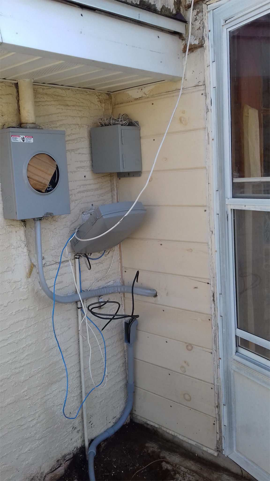
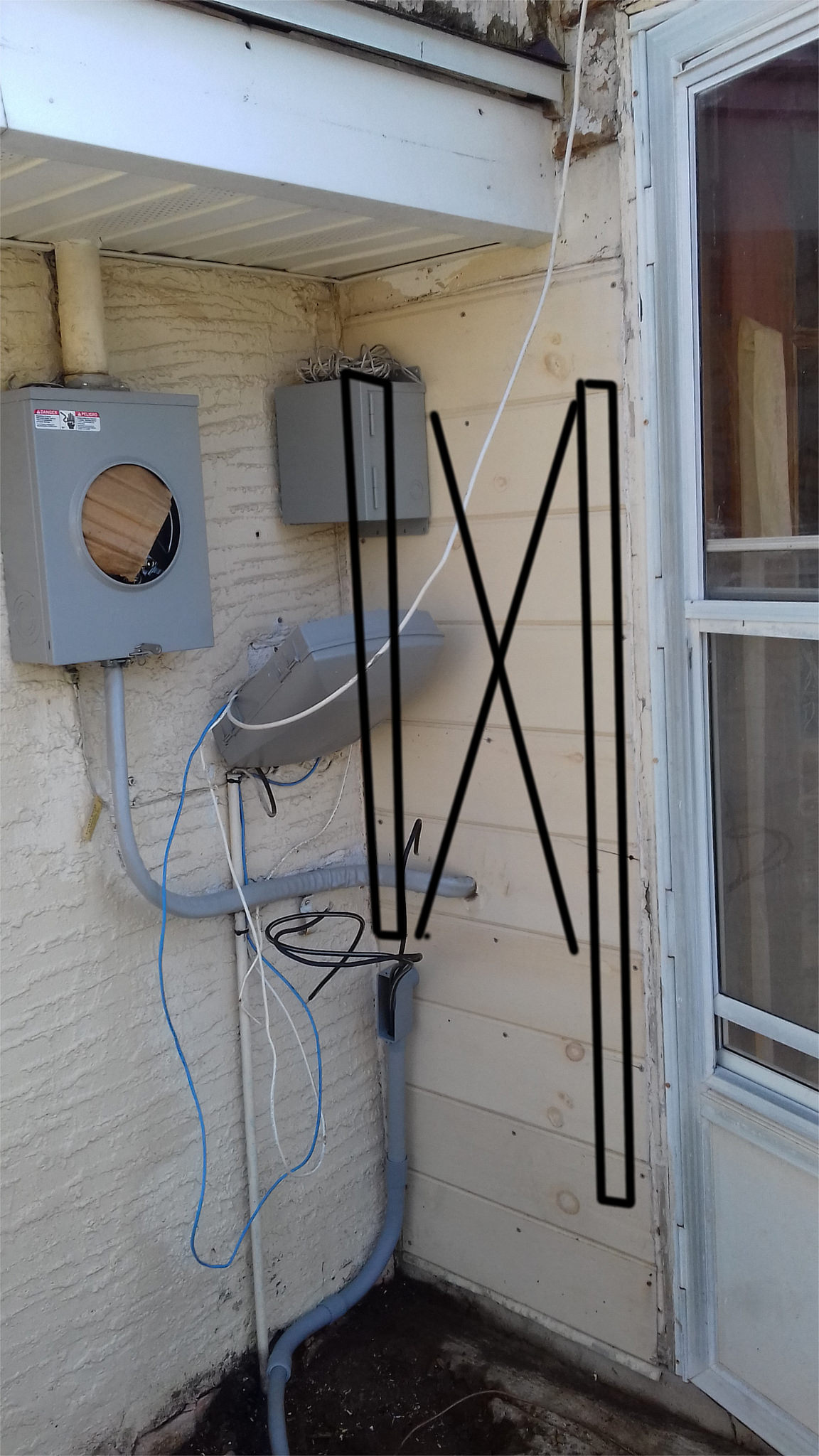
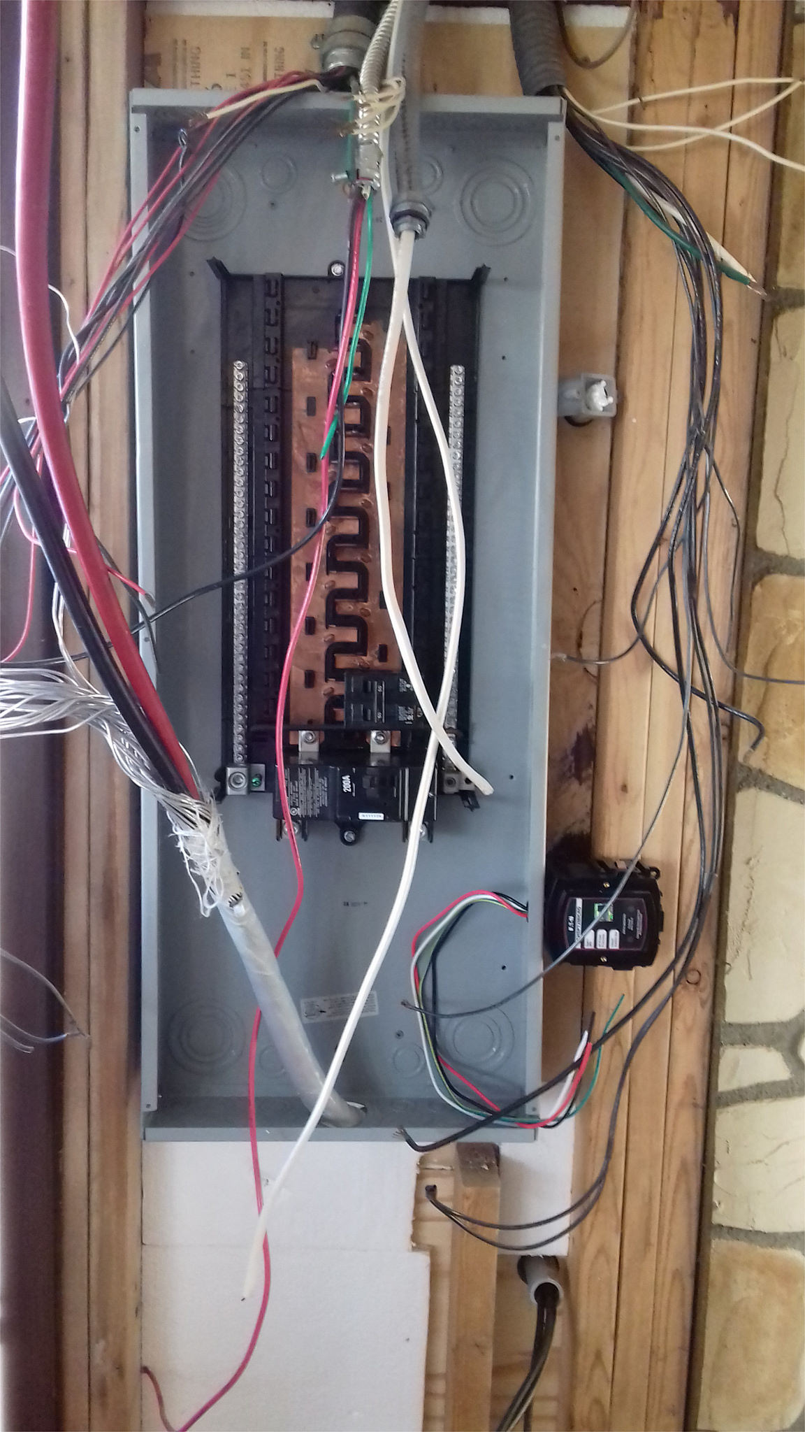
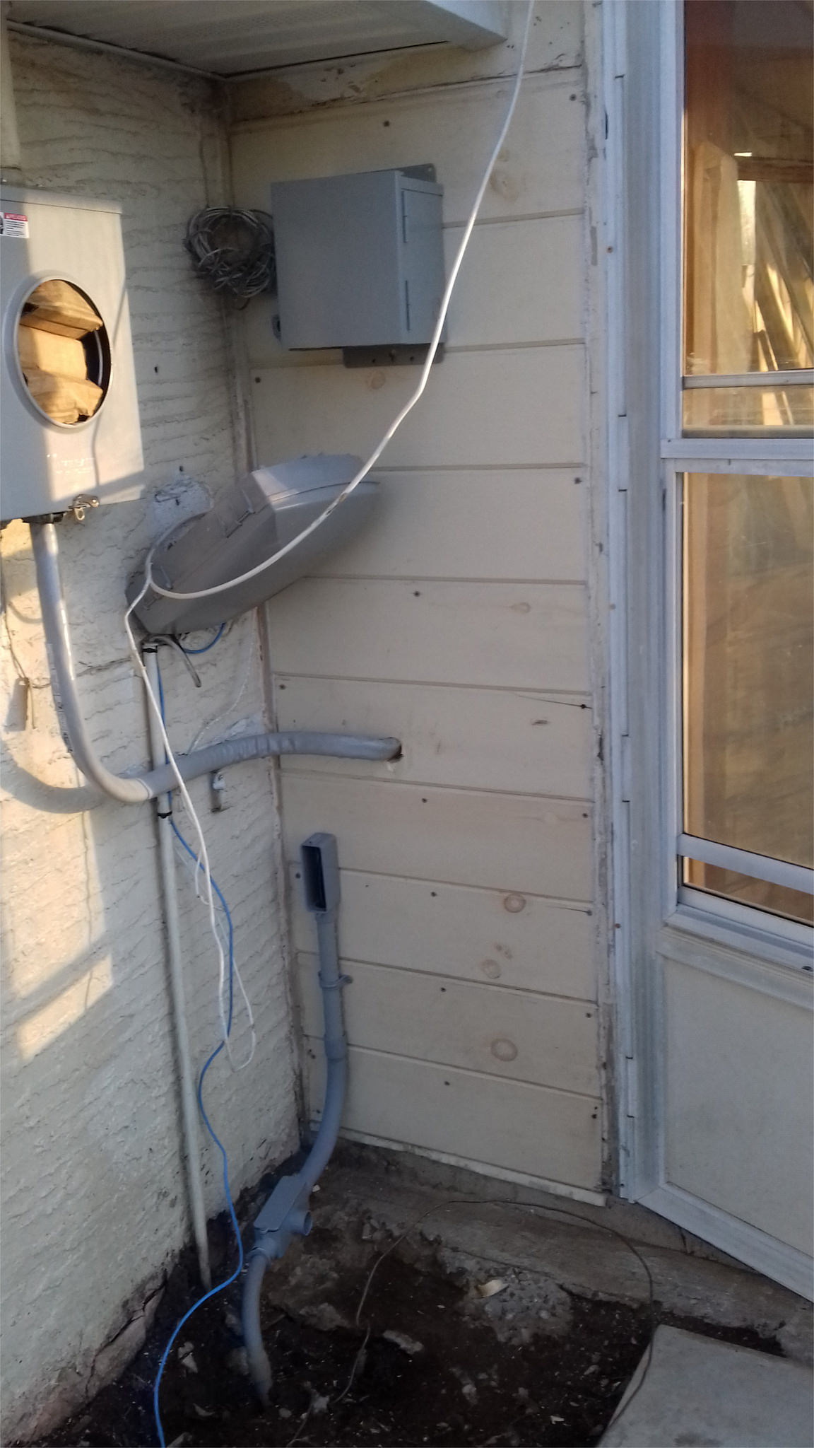
I finally got around to figure out the spot for a new transfer switch which I acquired some time ago. It is a small 5000 watts transfer switch (comes with relatives short wires), and it needs to be installed outside, and the only location outside would be on the same wall (exterior siding) whereon the circuit breaker panel hangs inside (interior of the premises). But then this wall (shown in the pic) is narrow and is sort of cramped and crammed with wires and stuff (socket meter nearby, conduits going up and down). The transfer switch in this case is a metal box hanging up on the wood sidings (the circuit breaker panel is right behind it. But I am not sure if this spot is ok, and what would be the requirement of clearances if any.

I finally got around to figure out the spot for a new transfer switch which I acquired some time ago. It is a small 5000 watts transfer switch (comes with relatives short wires), and it needs to be installed outside, and the only location outside would be on the same wall (exterior siding) whereon the circuit breaker panel hangs inside (interior of the premises). But then this wall (shown in the pic) is narrow and is sort of cramped and crammed with wires and stuff (socket meter nearby, conduits going up and down). The transfer switch in this case is a metal box hanging up on the wood sidings (the circuit breaker panel is right behind it. But I am not sure if this spot is ok, and what would be the requirement of clearances if any.