Rob:
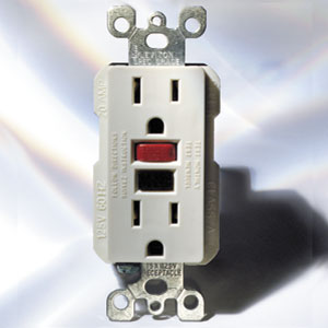
Are any of the outlets that have been affected GFCI's? (Groundfault Circuit Interrupter's) That is, do any of them look like this:
If so, then the problem is most likely that someone pushed the black "Test" button on the GFCI when pushing a plug into the GFCI. In that case, the red "Reset" buttom would have popped out, and you can restore power to the affected outlets by pushing the red Reset button back in.
If you can't find any GFCI's in your house (look in the kitchen and bath first, and then look everywhere else, even in the garage), or pushing the Reset button on any GFCI's you find doesn't help, then read on...
The first step would be to buy a digital multimeter so that you can confirm that there's 110 volts AC at the screw terminal on the circuit breaker.
Here is a blurb I wrote up years ago explaining how house wiring is typically set up. You would do well by reading it and asking any questions to straighten out any confusion.
Welcome to Basic Household Wiring: (this write up is longer than 10,000 characters, so I had to break it into two posts)
The wires that run overhead to your house carry 220 volt power. That 220 volt power is delivered via two power lines and a neutral wire. In practice, the two power lines will have black and red insulation on them, and the neutral wire will have white insulation on it. You will probably also encounter "ground" wires which have either no insulation or green insulation.
The two power lines each carry 110 volts AC, but they are "out of phase" by 180 degrees. That is, when the black power line is at +110 volts with respect to the white neutral wire, the other red power line will be at -110 volts with respect to the white neutral wire, and vice versa. So the voltage you would measure between each of the two power supply lines and the white neutral wire would be 110 volts AC, but the voltage you would measure between the black and red power lines would be 220 volts AC.
The standard 110 volt circuits for the ceiling lights or electric outlets in your house are made by connecting those lights or outlets between the white neutral wire and EITHER the red power wire OR the black power wire coming into your house. All of those connections are made in your electrical panel and a fuse or circuit breaker is provided for each such circuit in your house. So, some of the 110 volt circuits in your house that go to lights or electric outlets or fans are powered by the red wire, and some are powered by the black wire. As long as the circuit is between the red wire and the white wire, or between the black wire and the white wire, you have a 110 volt AC circuit. If you put a 15 amp fuse or breaker on that 110 volt circuit in the panel, then you have a 110 volt 15 amp circuit, and normally household circuits are in fact 110 volt 15 amp circuits. Newer houses often use 20 amp breakers for the electrical outlets in the kitchen because these outlets often have high demand appliances plugged into them, like toasters, microwave ovens, electric frying pans, etc.
So, if you look at a typical circuit going to a ceiling lamp (say), then you would have a 15 amp fuse or breaker on one side of the electrical panel or the other. The 12 or 14 gauge two conductor cable that goes to the ceiling light will have a black and white wire inside it. The black wire will connect to the 15 amp fuse or breaker and the white wire will connect to the "neutral bus bar" inside the panel. So, even if the fuse connects that black wire to the red voltage source, the wire will still have black insulation on it, so never presume that wires with the same colour of insulation are connected to the same voltage source. The cable with that black and white wire will go to an electrical box with a switch in it. The black wire will connect to a screw on one side of the light switch, and the white wire will terminate inside the electrical box. Another cable with a black and white wire in it will go from the switch to the light fixture. One end of the black wire in that second cable will be connected to the switch and the other end will be connected to the light fixture to supply power to the light bulb. The white neutral wire from that second cable will also be connected to the light fixture, to allow power to flow out of the bulb and back to the generating station. The other end of that white wire will connect to the white wire from the first cable that terminated in the switch's electrical box. So electrical power might come in the red wire from the generating station, go into a 15 amp fuse and then go along a black wire to a switch. That switch would stop or allow power to flow through another black wire to the light bulb, and then the power would flow back to the neutral bus bar in the electrical box via the white wire.
Simple enough, right? Well, household circuits can be that simple, but most often they aren't. That's because for a purely resistive load like an incandescent light bulb, Volts X Amps = Watts. So, in our circuit we have 110 volts delivered to a 60 watt light bulb, and according to that formula, our circuit is only carrying six elevenths or an amp, or 0.54 amps. Since the circuit breaker or fuse will allow up to 15 amps through that circuit, we have plenty of capacity in that circuit to power other things. So, typically there will be more than just a single light bulb on a household circuit. Other circuits (to electrical outlets or a ceiling fan, say) might connect to our circuit at the electrical box where the switch is.
220 volt circuits for the house's electric stove and electric clothes dryer are made by connecting the circuit between the main black and red wires at the electrical panel. Both the red and black wires carry 110 volts AC with respect the the white neutral wire, but because they're 180 degrees out of phase, there's 220 volts AC between the red and black wires. So, if you connect a circuit between the main black and main red wire going into the house, then you have a 220 volt circuit. If you're wiring a range, you normally need a 50 amp circuit, which requires a 50 amp breaker on BOTH the red and black wires going to the range. That means, you have to have a 50 amp breaker on the black wire going to the range and a 50 amp breaker on the red wire going to the range. And it also means you have to trip BOTH breakers before there's no power in the range, so you can work safely on it. If you're wiring an electric dryer, you need a 30 amp circuit, so that means you must have 30 amp breakers on both the red and black wires going to the dryer. On appliance wiring diagrams for 220 Volt AC appliances, like stoves and electric clothes dryers, the two power lines will typically be called "L1" and "L2" for "Line 1" and "Line 2".
When you open a typical electrical panel you'll notice that the fuses or circuit breakers are typically arranged in two vertical rows; one on each side of the panel. Do not assume that one side of the panel is for tapping off the red power line and the other is for tapping off the black power line. The buss bars inside the electrical panel determine what gets connected where, and often breaker positions above one another on the same side of the panel will be connected to opposite voltage sources. This is done so that the circuit breakers can be "ganged together" so that you can't flip the breaker off to one power line going to a stove or dryer without turning the power off to BOTH power lines at the same time. In Manitoba, where I live, the electrical code requires that circuit breakers for 220V appliances be "ganged" together in this way for safety reasons.
The technically incorrect but easiest way to think about this is that the power comes "in" on the red and black wires and goes "out" on the white wire. Obviously it doesn't because AC voltage is power that's flowing one way and then the other every 120th of a second, but that way of thinking about it will at least help you better understand house and appliance wiring and the reasons behind doing certain things certain ways.
For example, there is a standard wiring convention when wiring 110 volt electrical outlets and plugs. You will notice that the screw connections on one side of the duplex receptacle will be chrome plated, whereas those on the other side will be bare brass. Always connect the light coloured wire (the white neutral wire) to the light coloured screw (the chrome plated screw), and the dark coloured wire (the red or black wire) to the dark coloured screw (the bare brass screw).
Similarily, on 110 volt three prong plugs, you'll notice that the screw for the wider prong is chrome plated and the screw for the narrower prong on the plug is bare brass. You follow the same convention when wiring a plug as you do a receptacle. The light colour wire goes to the light colour screw and the dark colour wire goes to the dark colour screw (and the ground wire goes to the round prong). Remember this next time you're fixing an extension cord. If you mix things up when replacing the end on an extension cord, then the wiring convention doesn't help keep you any safer whenever you use that extension cord.