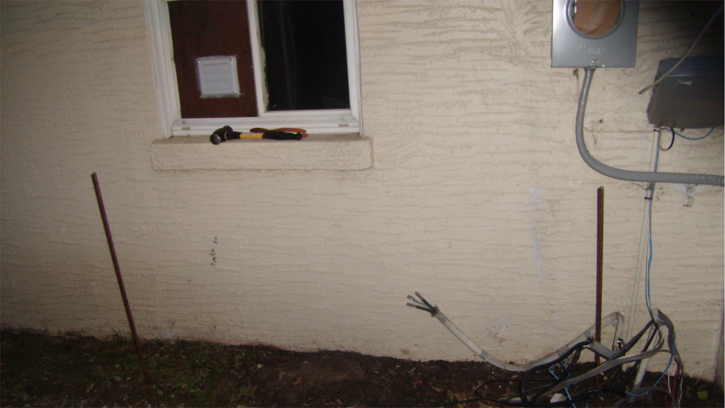
At the location near the service entrance and near the circuit breaker panel I driven and installed two ground rods at the required depth and required distance from each other. I was wondering about the impedance though, that is a good point; and nobody talks about it. As a matter of fact there are three ground rods near the circuit breaker panel (one is an old one that I decided to don't use unless needed).
I was not writing about the Service Equipment at your house. I was only writing about the Garage Installation that you showed a photograph of. Now that you have written about the service equipment though I will point out that you should bond all three ground rods together even though one of them is older and seems superfluous. You don't want any conductive underground objects of any description left near to and yet unconnected to the Grounding Electrode System of your Service Equipment. The differences of Potential between two underground objects can cause a voltage gradient across the surface of the ground which would be dangerous to people or animals including family pets. One way to effectively raise the voltage across a piece of ground is to have underground conductive objects that are not bonded to each other that may cause the current flow from a lightning discharge to flow more strongly in one direction between the Grounding Electrode System; in your case your two driven rods; and an abandoned rod in its flowing out into the entire space around the strike until the discharge is dissipated.
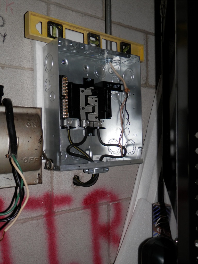
So there is not need for an ground conductor in the garage. But then there is no harm in having a EGC (one ground rod only) near the garage building and connected to the subpanel. I have electronic sensitive equipment so I may install a EGC there. The old subpanel had a bus bar and a ground bar in spite of having no ground rod installed for the garage structure.
The harm in having one rod only at your garage is that it would not be a code compliant installation unless the Single rod that you installed had an impedance to ground of Twenty Five Ohms or less. I'm trying to tell you that you must wire the garage's Building Disconnecting Means the same as if it were supplied by a separate service from the electrical utility. The only difference between the two installations is the formal name of them in the code. That would not be true if the Feeder included an Equipment Grounding Conductor (EGC) but your garage feeder does not.
250.32 Buildings or Structures Supplied by a Feeder(s) or Branch Circuit(s)
(A) Grounding Electrode. Building(s) or structure(s) supplied by feeder(s) or branch circuit(s) shall have a grounding electrode or grounding electrode system installed in accordance with Part III of Article 250. The grounding electrode conductor(s) shall be connected in accordance with 250.32(B) or (C). Where there is no existing grounding electrode, the grounding electrode(s) required in 250.50 shall be installed.
Hmm... The means of a main disconnect is not present at the moment; so I would need to have a main breaker or an extra disconnecting panel? And since the subpanel does not have a spot for a main breaker there is no main disconnect in the subpanel. But the subpanel is tied to the main circuit breaker panel at the house by means of a 60 amps circuit breaker, wouldn't that suffice as a main disconnect?
As you can see by the language in 225.32 below the Building Disconnecting Means may not be located in another building except under exceptions that never apply to dwellings. Just like the Service Equipment and the Service Disconnecting Means at your house, your garage must have Building Disconnecting Means consisting of switches, breakers, or pullout fuse holders that can be turned off with no more than six "throws" of the hand. The required Building Disconnecting Means must be located either outside the structure OR inside "nearest the point of entrance of the conductors." The best remedy in your case is to buy a tie down kit made by the manufacturer of the panel that anchors a two pole breaker to the panel so that it cannot be removed without tools. That Breaker becomes your Building Disconnecting Means when you connect the two energized (Hot) conductors of your feeder to it's terminals so as to feed current from it's terminals through it's mechanism, through the buss bar clamps on that breaker's bottom, and into the buss bars to supply the remaining breakers which are connected to the buss bars.
225.31 Disconnecting Means
Means shall be provided for disconnecting all ungrounded conductors that supply or pass through the building or structure.
225.32 Location
The disconnecting means shall be installed either inside or outside of the building or structure served or where the conductors pass through the building or structure. The disconnecting means shall be at a readily accessible location nearest the point of entrance of the conductors. For the purposes of this section, the requirements in 230.6 shall be utilized.
225.33 Maximum Number of Disconnects
(A) General. Th e disconnecting means for each supply permitted by 225.30 shall consist of not more than six switches or six circuit breakers mounted in a single enclosure, in a group of separate enclosures, or in or on a switchboard or switchgear. There shall be no more than six disconnects per supply grouped in any one location.
Exception: For the purposes of this section, disconnecting means used solely for the control circuit of the ground-fault protection system, or the control circuit of the power-operated supply disconnecting means, installed as part of the listed equipment, shall not be considered a supply disconnecting means.
(B) Single-Pole Units. Two or three single-pole switches or breakers capable of individual operation shall be permitted on multiwire circuits, one pole for each ungrounded conductor, as one multipole disconnect, provided they are equipped with identified handle ties or a master handle to disconnect all ungrounded conductors with no more than six operations of the hand.
225.34 Grouping of Disconnects
(A) General. The two to six disconnects as permitted in 225.33 shall be grouped. Each disconnect shall be marked to indicate the load served.
Exception: One of the two to six disconnecting means permitted in 225.33, where used only for a water pump also intended to provide fire protection, shall be permitted to be located remote from the other disconnecting means.
I will have a 30amps charging stations located inside the garage in order to charge a EV vehicle, and the other 30amps should be more than sufficient for my tools and lights.
Thanks for your insights!
The panel appears to be Eight slot. Is that correct? If it is eight slot will the remaining six slots be enough for the loads you will have in the detached garage? The back fed main breaker is Two slots. Your charging station is One or Two breaker slots depending on whether it is 120 or 240 volts. Will the remaining Four or Five slots be enough for the loads you have planned?