What the Heck is this Fan Capacitor?

House Repair Talk

Help Support House Repair Talk:

This site may earn a commission from merchant affiliate links, including eBay, Amazon, and others.

digitalbum

Active Member
Joined
Jun 10, 2013
Messages
30
Reaction score
7
Location
Louisiana
Need some serious help here (well, I'm not dying or anything, but my 3-speed ceiling fan is).

Ok, so I have SCOURED the interwebs for what a capacitor is and the only thing I can come up with is that it somehow allows for a ceiling fan to have 3 speeds (or the model capacitor I bought). Or something.

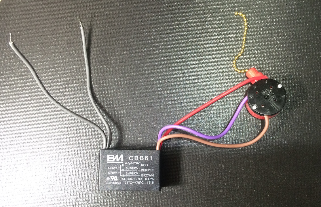
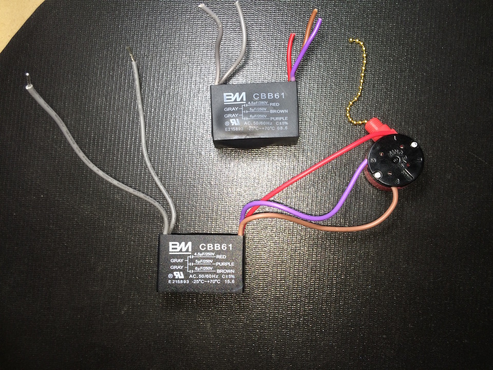
And the model I bought on amazon is the exact one I'm trying to replace, which is all mutated and I think has a goiter. The model is in the pics.

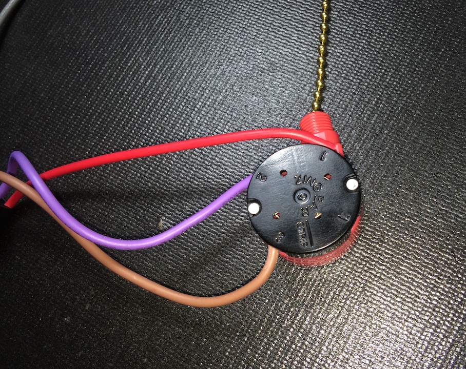
I probably have it rewired wrong (JUST the pull chain and capacitor) cuz I don't know what the "L" means. I think I've got the 1, 2, 3 correct. Maybe not.

Either way, after I get it right, how do I install it into my fan (pics below)?

Like, what are the 2 gray capacitor wires for? Do I need them both? And what about the ceiling fan wires? I snipped 3 that were connected to the capacitor/pull chain just to get them off.

(yeah I know I shoulda taken PRE pictures)

anyway, here's what I got...


33RP3Yu.jpg


SxWwVHI.jpg


hwwo6BF.jpg


and the ceiling fan wires:


LU3I3pn.jpg


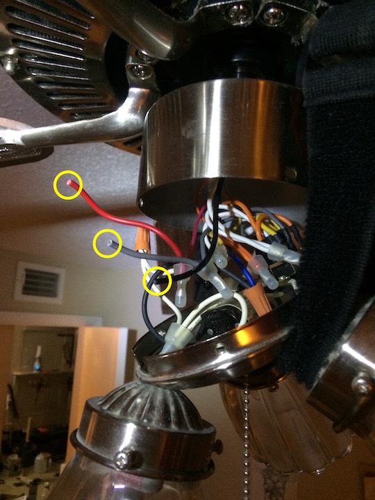
the other thing, sidenote, I had turned off my main breaker switch just to be sure, and I STILL got a tiny shock trying to pull out the pull chain wires. was the from the capacitor? or is that black ceiling wire the culprit?

anyway, i'm dumb, so pwease help!
 
You were right on the pre-picture.

I'm not sure any two ceiling fans have the same colored wires that do the same thing. If you can't find the 5 wires you cut and match them up with the colors on your switch/cap, your in trouble.
 
You were right on the pre-picture.

I'm not sure any two ceiling fans have the same colored wires that do the same thing. If you can't find the 5 wires you cut and match them up with the colors on your switch/cap, your in trouble.

I don't live in the past and do not accept this advice.
 
Sorry, but I got nothin, except this:

[ame]https://www.youtube.com/watch?v=Or7P9jfhcZ0[/ame]
 
That is not a capacitor. It is a resistor for the multi speed fan motor.
 
Your capacitor is rated for 250V, I suspect the 2 gray leads are for your 240V line from looking at the wiring diagram. However since you most likely have 120V at your fan, my guess is that only 1 lead needs to be connected and the other capped off. Without knowing for sure how the old one was connected I cannot tell you with complete certainty that is the way to do it.
 
Also that shock you felt was probably the capacitor. They can still hold current for a period of time after the power is turned off.
 
Makes sense Neal, gray leads are one for forward and other for reverse. They should have that identified on the unit schematic, it simply appears it's drawn as Line and Line.
 
Your capacitor is rated for 250V, I suspect the 2 gray leads are for your 240V line from looking at the wiring diagram. However since you most likely have 120V at your fan, my guess is that only 1 lead needs to be connected and the other capped off. Without knowing for sure how the old one was connected I cannot tell you with complete certainty that is the way to do it.

Yessir, that is something i recall reading. The 2nd Lead (ok, that's what it's called, I'm learning!) was indeed capped off by some other online dude.

Also that shock you felt was probably the capacitor. They can still hold current for a period of time after the power is turned off.

I think you're right. It was great.

Speedbump's on the right track; if you still have the wire nuts that you snipped off, you can see the color matched connections. If not, try to remember real hard ;).

Lol. I did manage to consolidate all the snipped and pulled-out wires, so it would like a little jigsaw puzzle.

ALAS, this has proven to be over my head, or rather, past my patience, so I just called the apartment maintenance. Yeah yeah, why didn't I do that in the first place? Cuz I'm a MAN!!(child :confused: )


thanks for all the help, mostly, I was trying to understand the fundamentals here, which I did, a bit, but I'll leave it to the "pros."

I will just annoyingly watch them while they work.
 
Will this help

Yes! thanks, but the maintenance dudes should be here today.

I finally cracked.

I just can't believe how difficult it has been to locate a manual or instructions for this thing online. I mean, this specific capacitor got 357 reviews on Amazon (4.7/5 stars) so I'd think there'd at least be SOME kind of manual for simpletons.

I found a lot of diagrams like that one, which is maybe the best, but turns out, e-lektricity is a cruel mistress. Especially when it's 40 wires seemingly crammed into a ceiling fan housing like a miniature Labyrinth (David Bowie, anyone?).
 
Will this help
Looking at the pics of the switch old and new and the fan wire housing, you've cut 5 wires to remove the capacitor and the 3-speed pull switch.
The 3 wires on the new capacitor comes with 3 wires factory attached to a new 3-speed switch.
So we only have to account for 2 wires that you cut; the two grey wires from the capacitor. However, the fan housing wiring show 3 cut wires - black, grey and red.
If you can see where the black, grey and red wires go, we can get this up and running.
In the housing, I suspect the black wire is power, the grey wire leads to the reversing switch but, can't figure out what the red wire is based on the pic.
Can you tell me what you see or post a pic of the insides?

Thanks to Nealtw, I think we've found what was missing for your new part.

You may not have separate feed for the light.
 
Back
Top