Weather Head to Socket Meter SER/SEU Cable Upgrade

House Repair Talk

Help Support House Repair Talk:

This site may earn a commission from merchant affiliate links, including eBay, Amazon, and others.
WyrTwister:

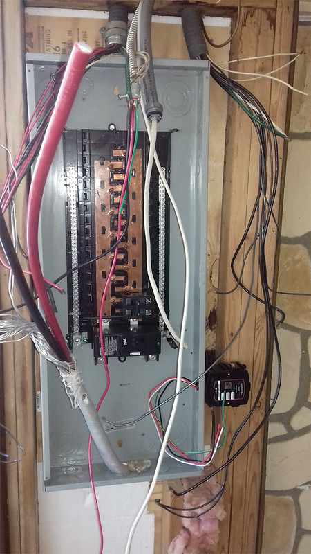
I got what seems a very nice 200 amps Siemens circuit breaker panel about a year ago: it comes with a copper ground rod, the buses are all copper, and it is really very large. I don't have the panel in front of me to look, but as far as I can remember there is a copper rod bonding the neutral bar to the ground bar.

hornetd:
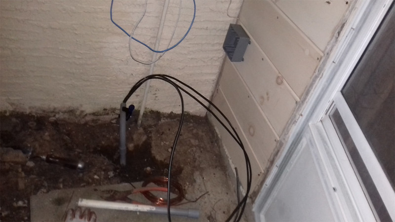
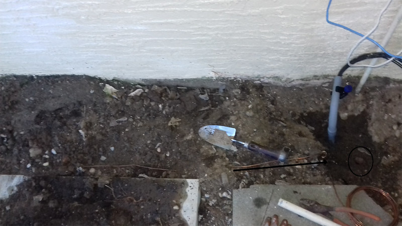
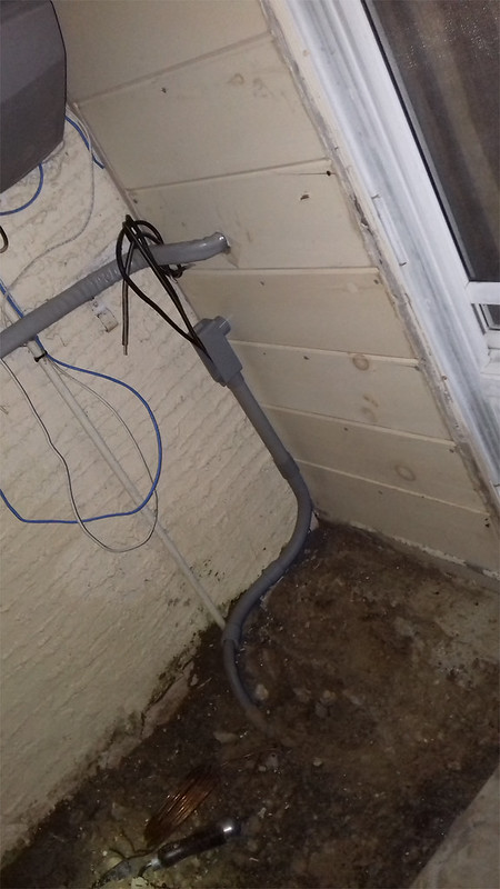
The weather head is right above the socket meter to wherein the service entrance cables descend into, the ground rods are just below the socket meter box besides the foundation and footing of the house (maybe 2 feet from and along the exterior walls) and the path that the ground wire travel is very short (maybe 12 ft all inn all ). And they all convert to the circuit breaker panel which maybe 5 feet from the socket meter. Besides, at the end of the day the area where the ground rods reside together with the ground wire will be covered with ground, landscape fabric, and river rocks (so hopefully no plants and weeds will dare to grow in there). Anyhow, I don't have a problem put it in a conduit once it exits the ground (can not be in a conduit at the segment that is connected the ground rods). Is Schedule Eighty Non Metallic Conduit (NMC) a form of pvc or liquidtight conduit (flexible)?

Don't worry, it will never be exposed to anything remotely close to physical damage. But just in case and to avoid any possible fuss I can put it inside a very short conduit.

thks!
With the ground cover that you describe and no adjacent driveway or parking I cannot see any inspector calling your Grounding Electrode Conductor (GEC) as exposed to severe physical damage. Since you are using #4 AWG wire no further protection will be required.

Schedule Eighty Non Metallic Conduit is just PVC conduit with thicker wall. It is not at all flexible.

If you have yet to install the driven rod Grounding Electrodes you have an opportunity to vastly improve the surge and spike protection of your home's wiring system by installing them in a way that is more effective than what the National Electrical Code (USA) requires. The US National Institute of Standards & Technology (NIST) guidance on a more effective Grounding Electrode System is to drive the first of two Eight foot long driven rods through the bottom of a trench that has been dug to a depth of Three feet. The rod should be it's own length from any underground structure such as footers or foundation walls. The Second rod should be at least the total length of the two rods away from the first rod. The Second rod should also be it's own length away from any underground structure. If the structure is slab on grade then both rods can be adjacent to the outer wall if the Three foot depth to the top of the rod puts it below the bottom of the footer. The two rods are then connected to the Grounding Current Carrying Conductor of the service at any accessible point between the drip loop and it's termination at the Service Disconnecting Means. The GEC that is used to make that connection should be Number Two AWG or larger bare copper buried in the bottom of the Three foot deep trench for a length of at least Twenty feet.

The last step in protecting your entire wiring system from damage caused by Current Surges and Voltage Spikes is to install a whole house protector that integrates the protection of all metallic conductor carried electrical currents which enter your home in a single place. Such multi service protectors are available from a number of manufacturers and the cost is quite manageable.
 
Good to know no normal inspector would create any issue with what seems a non-issue matter. I also plan on digging a small trench (maybe 4 inches deep) in order to have the bare copper #4 wires traveling inconspicuously. Then the wire would enter a small hole drilled in the siding, and then once inside up it would go to the breaker panel ground bar.

"If you have yet to install the driven rod Grounding Electrodes you have an opportunity to vastly improve the surge and spike protection of your home's wiring system by installing them in a way that is more effective than what the National Electrical Code (USA) requires. The US National Institute of Standards & Technology (NIST) guidance on a more effective Grounding Electrode System is to drive the first of two Eight foot long driven rods through the bottom of a trench that has been dug to a depth of Three feet. "

=> Unfortunately I already drove the ground rods (took me some time due to the may rock sediments lower in the soil).

"The last step in protecting your entire wiring system from damage caused by Current Surges and Voltage Spikes is to install a whole house protector that integrates the protection of all metallic conductor carried electrical currents which enter your home in a single place. Such multi service protectors are available from a number of manufacturers and the cost is quite manageable. "

=> The whole house protection is a really good option that I did not consider. Would I need the improved NIST grounding system in order to have a ground protection, or for it to work in a more optimum way? The only thing extra that I had in made was to install a Generator transfer switch outside the premises of the house (on the other side of the wall next to the circuit breaker panel).

Thanks!

The effectiveness of the whole house surge protection equipment would be greatly enhanced by installing the NIST grounding system but it is certainly worth installing even without the more extensive Grounding Electrode System. The most important practice is to make sure that all wire carried services use the same Grounding Electrode System to avoid differences of potential between the systems which would cause destructive currents to flow.
 
So, I am considering using a pvc weather sealed box on the siding to facilitate the entry of the underground wires into the building. Basically I plan on using pvc conduit besides the stucco wall and then it will turn and go up to the box (box is nicer than a plain hole and offers some protection).

I was wondering whether or not it would be ok to have the ground wire entering the building through the same pvc elect box that the the garage underground cable is using (the bare ground wire would not be encased in any conduit, it simply would enter though a small hole on the pvc elect box attached to the exterior wall and by doing that I would avoid drilling another hole on the wall for the ground wire and it would look nicer too)

Below is a pic depicting the situation:

24287410485_5ace455d2b_c.jpg


In the past I told there there is a third old ground rod bared, next to my new 2 ground rods recently buried. It turns out the the old single ground rod is right next to one of the new ones, so it would be easy to connect it as part of the chain; but the old ground rod upper end is severely deformed so i can not simply remove the clamp.... I was wondering if I could simply cut off the very end tip of the old ground rod in order to easy attach a new clamp and the new ground cable.

The old ground rod spot is circled in the pic below:

24287410535_2cd29d4c91_c.jpg


On the subject of a whole house surge protecion, I found this one at a local store:

http://www.homedepot.com/p/Eaton-Complete-Home-Surge-Protection-CHSPT2MICRO/202800798

was wondering if it would be an acceptable solution, or more expensive/high end would be required


thks!
 
That box is one way to bring the feeder conductors into the building but You may want to look at a conduit fitting called an "LB" instead. LB means an L fitting with it's removable cover on the back. I think that it presents a better appearance.
33340.JPG


There is no reason that you could not drill a hole into either the box or an LB to bring the Grounding electrode conductor into the building.

On the surge protection issue I would recommend that every wire that brings electricity in any form into your home be protected in the same device or at least at the same place.

Here is a picture of the single device approach.
243241-surgelogic-surgebreaker-plus-whole-house-surge


Here is a picture of the all in one place approach.
shopping


Notice that the device that you found at a local store is one of the devices in the second example. They are designed so that they will physically and electrically interlock when mounted so as to make all of the Surge Protection Grounding connections into a single bus bar. The reason that you need to protect all electrical pathways into your home in one assembly is that you do not want the extremely high voltage of a surge to cause a destructive current flow through one device on the way to ground via another electrical conductor that is attached to the same device. Take an LCD television as an example. It has a CATV connection, a power cord, and an internet cable attached to it. If a voltage spike that occurs on the power goes to ground via either the CATV coaxial cable or the Ethernet cable from your internet modem it will do so by forcing a destructive current flow through the components of the LCD television itself. If the all of those services are protected by devices that are attached with very short leads to the same buss bar then the current that flows is through the protective devices rather than through the LCD TV. That does not mean that you wouldn't want a portable protector at the LCD TV itself but it would not be subjected to any were near as severe a surge as was present at the point the effected wires enter your home.

Any Questions please ask.
 
hornetd:


Sorry the delay in my follow up with this thread. I tried to use ¾ pvc conduit but it was really difficult sleeve the wires inside the conduit, and I tried to use soap for no avail. So I ended up transitioning to 1" conduit (which made matters so much easier) by means of an adapter: I removed some of the old conduit protruding from the ground, and installed a ¾ 90d elbow there so that the conduit gets more or less level with ground till it arrives at the wall, after this elbow an adapter is used to transition to 1", then there is a 1" 45d elbow followed by some coupling and then another 1" 90d elbow, and from there there is a small segment of pvc conduit that goes to the small pvc box.

The following is the dry fitting so far:

24415006361_5c66274dab_c.jpg


Does this layout looks ok? I don't plan on glue it and simply use a press/dry fitting.

As far as house surge protection goes I was considering the Levington, but I heard that the eaton MICRO and ULTRA are also good options. The levington would take too much room (which means I would have to cut the studs, etc, in order to fit it). So I ordered the
eaton MICRO. Both the eaton ultra and micro work for the whole circuit breaker panel.
 
hornetd:


Sorry the delay in my follow up with this thread. I tried to use ¾ pvc conduit but it was really difficult sleeve the wires inside the conduit, and I tried to use soap for no avail. So I ended up transitioning to 1" conduit (which made matters so much easier) by means of an adapter: I removed some of the old conduit protruding from the ground, and installed a ¾ 90d elbow there so that the conduit gets more or less level with ground till it arrives at the wall, after this elbow an adapter is used to transition to 1", then there is a 1" 45d elbow followed by some coupling and then another 1" 90d elbow, and from there there is a small segment of pvc conduit that goes to the small pvc box.

The following is the dry fitting so far:

24415006361_5c66274dab_c.jpg


Does this layout looks ok? I don't plan on glue it and simply use a press/dry fitting. SNIP

With conduit you are only supposed to change size at a place where you can access the wires. In your case the conduit seems to be coming up out of the trench at a 45 degree angle. Best practice would be to bring it to straight up with a 45 degree elbow and change over to the 3/4 inch size by putting the reducing bushing into the back of an LB conduit body just like the one that goes into the house. the back cover of that LB would then be facing up. Off of the long end of the LB you would run whatever 3/4 inch fittings would allow you to reach the lower end of the LB that goes into the house. Since you cannot re-pull the conduit run anyway; because that size of wire should never have been pulled into one half inch conduit in the first place; making the change may seem pointless but having a reducing bushing at any place other than an accessible point screams rogue work. That is the kind of code violation that even a general home inspector may catch if you ever go to sell the house. Bonne chance.
 
Last edited:
hornetd:
As far as house surge protection goes I was considering the Levington, but I heard that the eaton MICRO and ULTRA are also good options. The levington would take too much room (which means I would have to cut the studs, etc, in order to fit it). So I ordered the
eaton MICRO. Both the eaton ultra and micro work for the whole circuit breaker panel.

What you install doesn't only have to protect the panel wiring but also the communications wiring. The most important aspect of the surge protection is that the protectors for the telephone and CCTV wiring must connect to the same grounding electrode system as the power wires with as short a lead and as close together as possible.
 
What you install doesn't only have to protect the panel wiring but also the communications wiring. The most important aspect of the surge protection is that the protectors for the telephone and CCTV wiring must connect to the same grounding electrode system as the power wires with as short a lead and as close together as possible.

I see the importance of having a triple protection with three different devices. Some people advocate three layers/tiers protection within the electrical circuit alone: one surge protection device at the meter socket, at the circuit breaker panel, andhen at the individuals outlets with outlet power surge strips, but at first it seems too much to have one at the socket meter too.

I could add one for the phone line and for the rg5/6 coaxial cable, but then the only thing have connected to the rg5 is an old motorola surfboard cable modem (I have a bunch of them around, can get them at ebay for $15); and in the remote chance of an overcurrent and voltage spikes to fry the cable modem circuit board there is not much of a loss there. I don't use landline/fixed phone, besides att internet service are absurdly expensive (and adsl/dsl modem are fairly cheap too). I know there is always a possibility of future services and upgrades, so I guess it is worth adding the ones for the phone and cable services.

Below is a pic of one attached to the panel (it is a closes to the main lugs as it could get):


23975039993_90e9f06fb3_c.jpg
 
With conduit you are only supposed to change size at a place where you can access the wires. In your case the conduit seems to be coming up out of the trench at a 45 degree angle. Best practice would be to bring it to straight up with a 45 degree elbow and change over to the 3/4 inch size by putting the reducing bushing into the back of an LB conduit body just like the one that goes into the house. the back cover of that LB would then be facing up. Off of the long end of the LB you would run whatever 3/4 inch fittings would allow you to reach the lower end of the LB that goes into the house. Since you cannot re-pull the conduit run anyway; because that size of wire should never have been pulled into one half inch conduit in the first place; making the change may seem pointless but having a reducing bushing at any place other than an accessible point screams rogue work. That is the kind of code violation that even a general home inspector may catch if you ever go to sell the house. Bonne chance.


Good to know that, but I fail to see the reasoning behind it. At an earlier post I indicated that the original conduit was 1/2", and that is not the case (my bad), in reality it is 3/4" so I am transitioning from 3/4 to 1" because it was a breeze to install compared to the 3/4"

In any case, the conduit coming out of the trench is a 3/4" pvc conduit with a 90d angle that I installed (with lots of elbow grease) which connects to the original 3/4" conduit cropping up from the ground, then there is a transition to 1" conduit and from that point on everything is 1". The adapter that transitions from 3/4 to 1" is on the surface of the ground (besides the wall), but by "access the wires" you mean in an electrical box (LB in this case)? It would be difficult to put an LB in that spots and everything aligned with the wall. Would it be required to visually aligned with the stucco wall (it still would be aligned going upward with the wood siding wall)?

thks!
 

Latest posts

Back
Top